PLC Simulation System
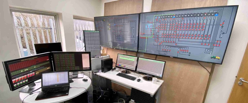
We have developed a PC simulation package to help in factory acceptance testing of control systems. We have found the traditional method time consuming and not easily transferable to the next project. Depending on the size of the project under test considerable amounts of lamp and switch boxes are sometimes required to be assembled.
We required a system that provided the same visual aspect as the old switch box and lamp arrangement but using a more modern PC / software approach.
Detailed below is the traditional method of testing a PLC system.
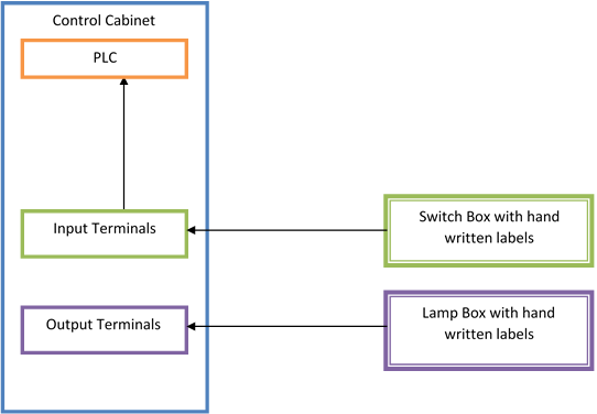
The previous diagram shows a control cabinet with a PLC connected to a switch box and lamp box, one of the main issues with this system is the considerable wiring involved for something that is only used at the factory testing stage, also all the lamps and switches have to be labeled.
During the factory test careful attention is required to ensure the switches are operated in the correct order as expected by the PLC program.
One fundamental point of the system is that if any documental evidence of the factory testing will have to be produced by hand, which can be time-consuming and error-prone.
Detailed below is our new method of testing a PLC system.
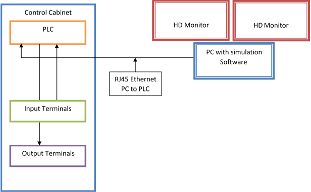
The above shows that using a standard PC with a custom designed simulation software which represents the external equipment.
This will be depicted on the screen as the element the PLC is expected to operate the valve, motor, pump, breaker etc.
A very useful feature is the addition of an event viewer, which has proven useful when performing the factory acceptance with the customer.
The event viewer keeps track of any event that occurs on the simulation PC, this includes any buttons or elements that are operated and also adds a time and date stamp.
There is also a provision to add a text comment in the event viewer window to help annotate a test procedure in line with any test documents used on the day, this log can then be given to you as evidence of the completed test.
Another advantage of our new systems is it helps with in-house testing prior to performing the actual FAT test at the customer’s site. We can achieve this as the only wiring required between the PLC and our simulation package is an Ethernet cable.
Also for future modification of an existing PLC system that requires modifications, the original simulation application which is normally saved along with the PLC and HMI programs can be modified and used to test the PLC against the revised requirements.
This becomes more important as the original control panel will be unavailable for any factory testing as this will installed onsite.
The simulation software uses an OPC server over Ethernet so any modern PLC which has an RJ45 connection can be used.
We have successfully utilized our simulation application with Advantech (Modbus TCP), Allen Bradley (RSLinx OPC) and Siemens (Simatic Net).
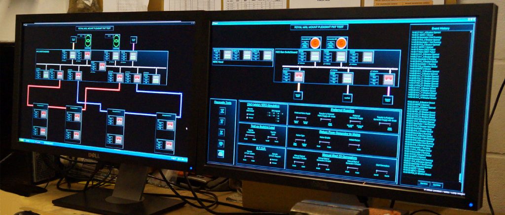
Below are two examples of where our PLC simulation system has been used, the first is a project we did for Royal Mail’s main sorting office in central London. The PLC and HMI equipment was an Advantech and used Modbus / TCP.
The screen shows the high voltage breakers and the two 0.8 MW generators. This picture was taken during the factory acceptance test at our panel manufacturers with our customer, client and main consultant.
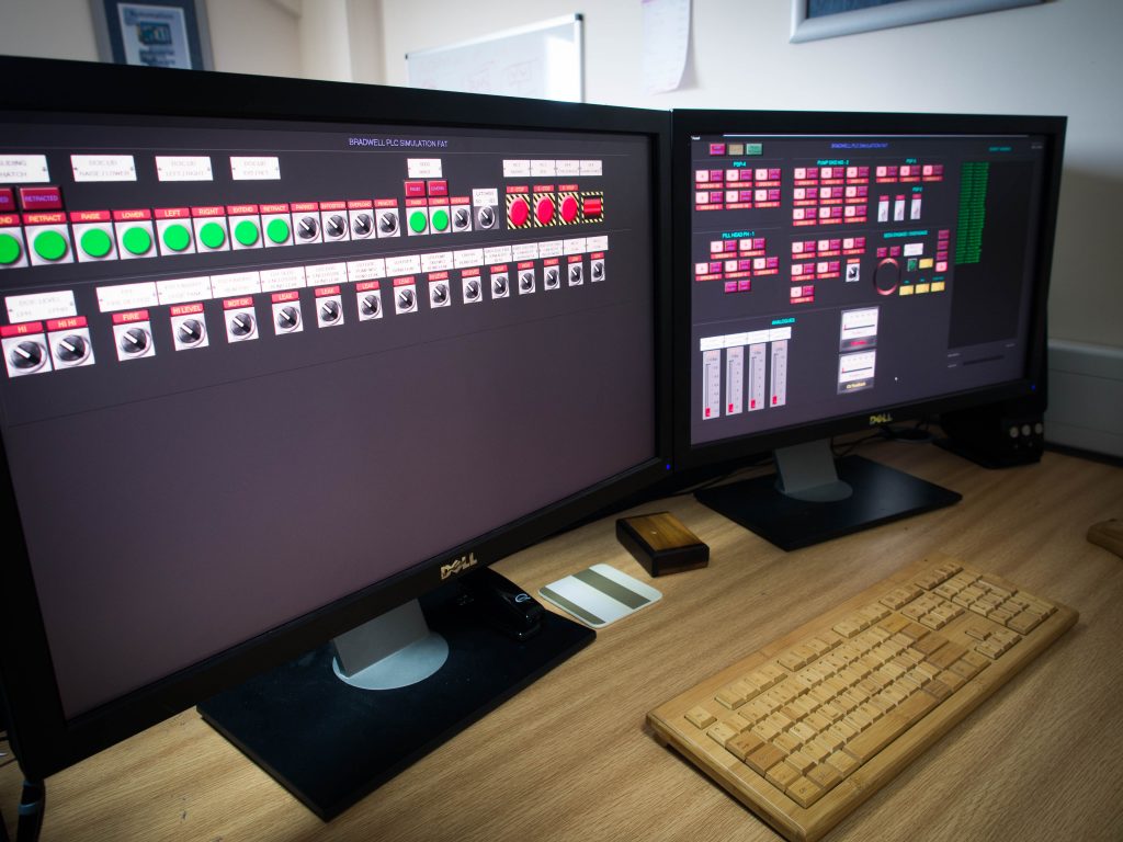
The second one is for Magnox, this is a nuclear facility at Bradwell Essex. This PLC was an Allen-Bradley CompactLogix with a PanelViewPlus HMI.
The screen shows the various valves, pumps, and cranes used to control the flow of nuclear waste throughout the plant. This was taken at our offices during the factory acceptance test.
